
Our bus build was schedule constrained, which meant that I didn't have time to do work twice. It meant planning things in the evenings and then executing those plans correctly the first time during the day. We weren't going to have time for a shakedown cruise, so it meant that everything had to be repairable and tweakable while underway.
This is a labelled picture of the bus, although the labels are difficult to read. Note that we snugged the components up under the floor so that we really don't lose any ground clearance. Up front on the driver's side is the power distribution box. All of the water tanks are behind the rear axle; the black tank is right behind the drivers wheel. You can see the white PVC pipe coming out of the window -- that's the vent stack for the black pipe.
Mounted on the passenger side, the big white box you can see is the 95gal fresh tank. You can also see the drain and dump plumbing back there. If you look very closely you can see two storage boxes ratchet-strapped to the bottom of the bus. These hold the hoses for fresh and waste water attachments.
From level ground,it's difficult to tell anything is installed on the bus at all, especially if the vent pipe is stowed. There is a ball valve inside the bus that actually closes the vent stack, which means I can disassemble it downstream of the valve and bring the pipe inside the bus to shut the window. Longer term the stack should go through the roof, but that's a tricky job to do correctly so I put it off for this year :)

What you are seeing is a SketchUp model of the bus floor and the black tank I ordered, with pipe stubs coming upward in the dimensionally accurate locations that I specified when ordering the tank.
I failed to fully account for the pipe diameters and floor construction when I ordered the tank. The inset photo shows that my vent stack pipe will interfere with the sheet metal C-channel that each segment of flooring is made of.
If I had done this model first, I could have moved the location of the vent hole an inch or so. When I got the actual tank delivered, and went to put it in place, I had the exact problem the 3D model predicted. Luckily, I fixed it by just cutting out a little of the sheet metal :)
Validating your design decisisons using a 3d model is much faster and cheaper than not validating them until you've ordered custom parts or cut materails. Furthermore, you can do your computer work late at night, or on rainy days, or when you're too sore to actually do bus work. Time you spend resolving design deficiencies in software always pays you back when you get under the real bus.

L-Track Rails L-Track, often called "Logistics Track", is extruded and machined aluminum rail. It is incredibly light and incredibly strong. It is used in the air cargo business, both civilian and military. It has started to show up on the consumer market for building trailers and for enhancing pickups.
Youtube clip I made where my older son helps me explain L-Track :)
The basic idea is that you install these rails, and the rails are drilled every inch for standardized fittings. A wide variety of fittings are available to help you secure different types of loads.
In my bus, I use L-track in a few places
How does L-Track help with creating an interface? Think about the bottom of your bus. It is not a flat uniform surface. You can only attach things in certain spots -- where there is something to screw into. In my bus, the floor was 9.5" wide sections of C-channel sheet metal. It was a highly irregular surface to try and mount things to.
Yet the placement of water tanks is pretty important. The black tank specifically must be in exactly the right spot, because it determines the location of the toilet. The toilet location drives the layout of the bus interior; the toilet location determines the location of the black tank; the underside of the bus provides constraints on where the black tank can go. The last thing we need is an inflexible mounting system for the black tank.
Enter L-Track. L-track lets me create an interface between an irregular bus floor and an object that has specific location requirements. I mounted the L-Track to the underside of the floor wherever I could find sheet metal to attach it to. I used about 20 fastener packages per 100" beam of L-Track. Each fastener package was quarter inch stainless, with fender washers and nylocks. The tensile strength of these bolts is tremendous; each rail has 20 of them supporting it, and rails are used in pairs. The rails themselves tie the floor sheet metal together at increments no further than 7 inches apart.

A doublearing L-track fitting is rated for a 4000lb static load
The L-track lets me mount fittings every 1", irrespective of what is going on with the floor of the bus. It lets me use a variety of different fastening techniques, and it lets me change my mind if something isn't working. It even made initial install much easier, as I could transition from temporary rigging (ratchet strap) to permanant rigging (J-hooks and angle iron).

L-track rails mounted to bottom of bus
In this photo, you can see the odd spacing of the floor sheet metal, and the two L-Track rails on either side of the "bay". This is version 1 of my power distribution box. It contains the master kill switch, master DC fusing, battery bank, inverter, shore-power interface, etc.
The rigging method used here is as follows. I use double-position rings in the L-track. I use long J-hooks coming down on either side of the load, and I use a peice of angle metal to go underneath the load. The basic pattern is repeated at whatever spacing interval I need and in whatever positions I require.
To hang this heavy and awkward box, I used ratching straps through temporarily fitted rings to lift the box and fine tune its position. When I was satisfied with it, I started putting in more rings and hanging the J-hook + angle metal cross bar assemblies. Then I removed the ratcheting straps. At that point, I loaded the batteries in from the back and connected the wiring.
I used the same approach to hang my 95 gallon fresh tank and my 25 gal black tank. For my grey tank, I mounted the L-track rails to the bottom of the frame rails, which meant using long J-hooks didn't make sense. There, I used a different type of L-track fitting which takes a bolt directly, and simply used bolts through angle metal to support and locate the gray tank.
I spent hours drilling and installing the L-tracks, which is low-precision, repetitive work. Because I did that work, the much tricker job of locating and installing the basement loads was made very easy.
My desire for field-adjustability paid off on our first trip. I didn't build a proper support box for my fresh tank, and as I began to put more and more water in it during the trip, I noticed that the tank was starting to sag/bulge between my support beams. If I had built a zero-clearance welded frame to hang this tank, I'd be in deep trouble. However, instead I purchased a peice of plywood, cut it to the size of the tank, removed most of my supporting beams, inserted the plywood, and re-attached my support beams. I did this in a parking lot and it took perhaps 90 minutes. Adaptability is a critical aspect of the skoolie experience.
I also used L-track on the inside of the bus. It is how my seats are attached. Those of you who have removed the original bus seats will recall how they were fastened -- just bolts through the sheet metal floor. On my bus, a handful of the fasteners went into the metal at odd angles or with zero clearance because of the under-floor geometry of the sheet metal. Furthermore, every seat bolt was a source of rust intrusion into the metal floor.
Here is a youtube video I did when I was installing the laminate flooring. It shows how I mounted the L-track for the seats, and how I "grew" the flooring around the L-track rails to create a nearly-flush installed height.
Contrastingly, with L-track, I created an interface. I screwed the L-track to the bus floor only where it made sense to do so. And then i attached the seats to the L-track precisely where I wanted them, with no concern for what was happening under the bus. L-track is also used in the bus industry -- but only for wheel chair fastening. I can actually position my seats anywhere I want to, in one inch increments. I don't have to change anything else.
PEX, on the other hand, is very fast to alter in the field -- if you have the right tools. While I cannot carry a pipe threading machine with me, I can certainly carry a pex crimper in my toolbox. And infact, I did so. I had a water leak that I detected while underway. Fixing it was no problem - I cut off the section of tubing that had a bad fitting, and put on a new fitting with a new section of tubing sliced in. It took me longer to buy the fitting at a big-box store than it did to do the repair.
PEX also turns corners and can be "stuffed" into crevies and nooks. It's great for a skoolie conversion. Buy a nice crimper and the $10 pex cutting tool, and you'll be set to go.
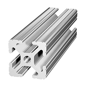
I am investigating the use of T-Slot framing to build additional structures within the bus. T-Slot framing makes use of extruded aluminum beams in standard sizes and profiles. You can calculate the performance of a given beam using free software, and the only cutting you do is to cut the beams to length. All other assembly is done via hand tools using T-slot fasteners.
T-slot beams are incredibly strong, incredibly light, and build a framework for modular upgrades. They also allow you to change your mind later, as apart from cutting the beams to length, nothing needs to be permanant. The aluminum never rots or rusts.
I am currently working on the design of the partition walls or bulkheads in the bus. These walls will separate the kitchen from the bathroom, and the bathroom from the bunkroom, and the bunkroom from the trunk area. I'm considering series 10 T-Slot framing, which means the beams are have a 1"x1" cross section. This means that the walls will be 1" thick. Compare this to 2x4 wall framing; I should have walls which are lighter, stronger, and take up less space.
Here is a mockup of what a bulkhead wall could look like.

Note that panels can be carried and enclosed by the T-Slot beams. There are panel fasteners you can use, but 1/4" panels can also rest inside the slots with no fastening required.
Pre-made door-hinges exist that bolt right into T-Slots, as do curtain hangers. Our initial plan would be to have a hanging curtain in the door, but we could trivially build a door using a few more T-slot beams and attach it using t-slot hinge hardware.
I am planning the use of the 1030 profile material to build the bunk bed frames. If you take a 7 foot 1030 beam and place a 300lb static load at its center point, it will deflect less than 1/8" inch. This simulates a large adult bouncing on the center of the front edge of the bed prior to getting in/out. Yet this beam is 1" thick and 3" tall.
Another plan I am considering is attaching more L-Track rails to T-slot bulkheads in the trunk.